Brain Computer Interfaces
Brain Computer Interfaces
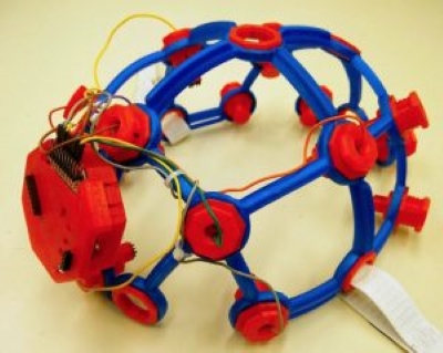
The 3D printed headset used for EEG recording.
In our lab, we’ve been working on Brain-Computer Interfaces (BCI).
At the moment, the project under development is related to a portable and cost effective P300 BCI for the control a robotic arm. In this project, to record the EEG signal OpenBCI, an open-source and affordable EEG acquisition system, is used. Together with it,as a support for the EEG electrodes a 3D printed headset is used. Thanks to it, the electrodes are stable throughout the recording.
Brain Computer Interfaces
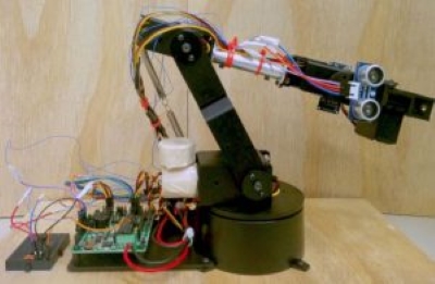
The robotic arm used as an output device for our BCI.
The robotic arm that we choose as the output device of our BCI is the Lynxmotion AL5B arm. It is a 4 Degrees of Freedom robotic arm, that can be controlled in an easy way with the BotBoarduino board. A force resistive sensor on the gripper and two ultrasound sensors on the sides of the arm are used to improve the level of safety of the robotic arm. Weights in the posterior part of the arm are added to assure stability.
Brain Computer Interfaces
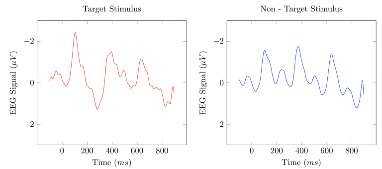
In the left figure, it is possible to see a positive peak at around 300 ms. That peak represents the P300 wave. In the right figure, no P300 wave is present since the stimulus presented is non-target.
By presenting to the user visual stimuli showing possible movements of the robotic arm, P300 waves are generated. The difference between the EEG recorded when a target or non-target stimulus is presented to the user is visible in the following figure:
Brain Computer Interfaces
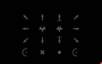
Example of visual stimuli used in the P300 BCI.
Logistic regression is used to classify the EEG signal. After performing the classification, the robotic arm moves according to the stimulus that generated the P300 wave. An example of the visual stimuli employed in our system is shown in the following figure.
Every 240 ms, a column or a row of this grid intensifies for 120 ms. The flash generated by this intensification represents a stimulus for the user, and a P300 wave will be present in the EEG signal if the movement he was focusing on is inside the row or column that flashed.